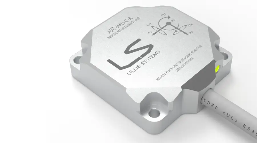
A2C-IMU
Inertial Measurement Unit — CAN Bus
Multi-axis inertial sensor with CAN Bus interface. Available with M12 or cable connector, in aluminium or stainless steel, with optional logic output.
From $229 USD / unit (qty 50–99)
Lillie Systems designs ruggedised inertial sensors and signal conditioners with CAN Bus and Ethernet connectivity — built for industrial automation, logistics, and aerospace applications worldwide.
Trusted by industry leaders


Precision-engineered for CAN Bus and Ethernet networks. Available in aluminium and stainless steel enclosures.
A2C-IMU
Multi-axis inertial sensor with CAN Bus interface. Available with M12 or cable connector, in aluminium or stainless steel, with optional logic output.
From $229 USD / unit (qty 50–99)
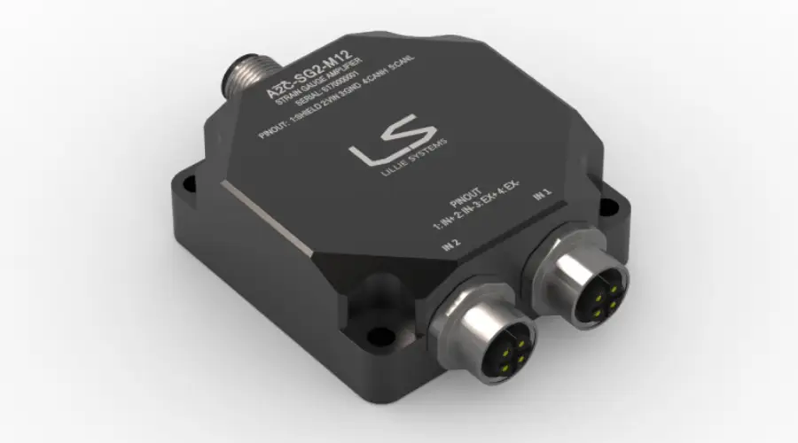
A2C-SG2
Two-channel strain gauge amplifier with CAN Bus output and M12 connectors. Available in aluminium or stainless steel enclosure.
From $280 USD / unit (qty 50–99)
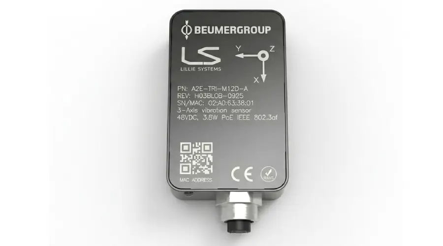
A2E-TRI New
Three-axis accelerometer with Ethernet connectivity and Power over Ethernet (PoE IEEE 802.3af). Plug-and-play network integration with no separate power supply needed.
— contact for pricing
Ruggedised aluminium and stainless steel enclosures rated for harsh environments, vibration, and wide temperature ranges.
Designed from the ground up for industrial bus protocols — CAN Bus (ISO 11898) and Ethernet including PoE IEEE 802.3af.
Deployed by leading manufacturers in automation, aerospace, energy, and logistics across multiple continents.
Technical guidance from sensor selection through to integration and commissioning, directly from our engineering team.
Tell us your application and we'll recommend the right sensor configuration.