Overview
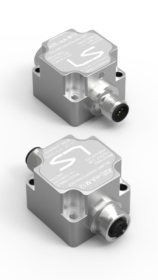
The A2C-mA-M12 is a 0-20mA analyzer that can measure 3 x mA signals simultaneously. The analyzer can calculate True RMS values, minimum, maximum values, average value and combine multiple inputs with mathematical calculations. For instance, the difference between two inputs can be calculated (can be used for differential measurements). Other math operations are the ratio, product, and sum of two channels. The results calculated can be used to trigger up to 6 different alarms with programmable thresholds.
The sensor can communicate the measurements to a host via CAN Bus or it can be used in a standalone mode without any CAN bus connected after initial programming with the U2C accessory. In the event of an alarm triggering, the logic output is activated, which can be used to drive a relay / buzzer / lamp or plc input.
The optional USB programmer (U2C) with free software, simplifies programming, and no knowledge of CAN bus communication is required.
Features
For each channel the following information can be requested over the CAN Bus:
- mA
- min / max value since last reset or last data request
- RMS value of mA
- RMS min / max value since last reset or last data request
- formatted values to represent a real sensor
- Mean value of mA
- Frequency of maximum signal energy (in testing)
The following math operation are available on all input channels, and both normal and RMS values can be used.
- Subtract one input from the other
- Add one input to another
- Multiply two inputs
- Divide one input with the other
- Ratio in % of two inputs
The following parameters are some of which can be programmed to trigger the logical output. The values to be checked can be the result of the math operations. For instance, the difference between two inputs can be setup to trigger when above a given value.
- Value higher than threshold
- Value lower than threshold
Some of the other features are:
- Programmable Bandwidth
- Heartbeat CAN messages with programmable periods
- Periodic CAN messages with programmable data and time periods
- Low power consumption
- Durable aluminum / stainless steel housing
- Software upgradable via CAN bus
Applications
- Differential pressure in hydraulic motors
- Hydraulic flow measurements
- Alarm if given pressure exceeds a given setpoint
- Monitor each outrigger leg for low pressure
- Alarm if given pressure falls below a given setpoint
Accessories
U2C
SimplicityUse the U2C programmer
No prior knowledge of CAN bus communication is required! You can check the U2C programmer and software here:
Program using U2C
Connect the U2C to your PC after installing the drivers and software. Connect the A2CTRI to the U2C and apply power.
Use free software
Using the free software, set the mode of operation and the alarm thresholds. View real time data from the sensor and have it shown graphically.
Install
Install the sensor in its application and verify that everything works as it should. It is still possible to connect the U2C and log the real world data, which can be used for analysis.
Examples of applications
Chassis Leveling - truck mounted crane
For a truck mounted crane, the A2C-TRI can detect if the chassis is within given angle thresholds. Each axis has programmable thresholds and hysteresis which is easily programmed with the U2C adaptor.
Chassis Leveling - arial platform
For an arial platform, the A2C-TRI can detect if the chassis is within given angle thresholds. Each axis has programmable thresholds and hysteresis which is easily programmed with the U2C adaptor.

